Controlled servo drives are used in many areas of automation technology, converting, printing, handling, and robotics, including production machines and machine tools. The selection of a rotary encoder or encoder technology for use within the system depends on the accuracy requirements of the application and whether the application will use position control, velocity control, or both.
Before making an encoder decision, engineers should examine this and all the major encoder properties that have the largest influence on important motor performance. These include:
- Positioning accuracy
- Speed stability
- Audible noise
- Power loss
- Bandwidth, which determines drive command-signal response
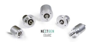
Need help choosing a rotary encoder for an automation project? Use Heidenhain’s selector tool to narrow your search fast.
Positioning accurating
Positioning accuracy depends solely on the application requirements. Resolvers, for example, mostly have one signal period per revolution. Therefore position resolution is extremely limited and accuracy is typically in the range of ±500 arcsec. Assuming interpolation in the drive electronics, this usually results in a total of 16,384 positions per revolution.
On the other hand, an inductive scanning system — as found in many rotary encoders — will provide significantly higher resolution, typically in the range of 32 signal periods per revolution, resulting in an accuracy in the range of ±280 arcsec. The interpolation in this case is internal to the encoder, resulting in 131,072 positions per revolution.
Optical rotary encoders are based on very fine graduations, commonly with 2048 signal periods per revolution, and therefore, even higher resolutions are possible with internal interpolation electronics. The output resolution here is 25 bits, which means 33,554,432 absolute positions per revolution with accuracies in the range of ±20 arcsec.
Speed stability
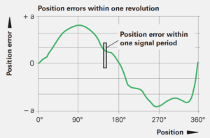
To ensure smooth drive performance, an encoder must provide a large number of measuring steps per revolution as the first piece of the puzzle. However, engineers must also pay attention to the quality of the encoder signals. In order to achieve the high resolution required, the scanning signals must be interpolated. Inadequate scanning, contamination of the measuring standard, and insufficient signal conditioning can lead to the signals deviating from the ideal shape. During interpolation, errors can occur whose periodic cycle is within one signal period. Therefore, these position errors within one signal period are also referred to as “interpolation errors.” With high-quality encoders, these errors are typically 1 to 2 percent of the signal period, as demonstrated in Figures 1 and 2.
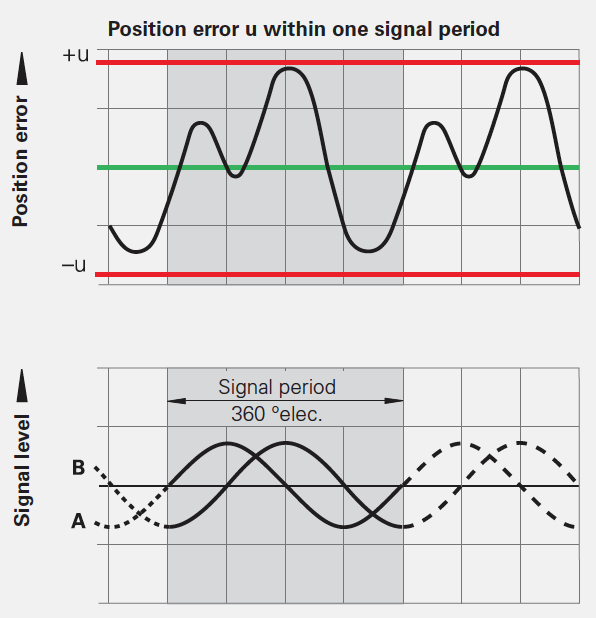
The interpolation error adversely affects the positioning accuracy and significantly degrades the speed stability and audible noise behavior of the drive. The speed controller calculates the nominal currents used to brake or accelerate the drive depending on the error curve. At low feed rates, the feed drive lags the interpolation error. At increasing speeds, the frequency of the interpolation error also increases. Since the motor can only follow the error within the control bandwidth, its effect on the speed stability behavior decreases as speed increases. However, the disturbances in the motor current continue to increase, which leads to disturbing noises in the drive at high control loop gains.
Higher resolutions and accuracies also reduce disturbances in the motor current in the way of heat generation and power loss. Figure 3 shows a simple comparison of three different scanning technologies and the resulting current draw.
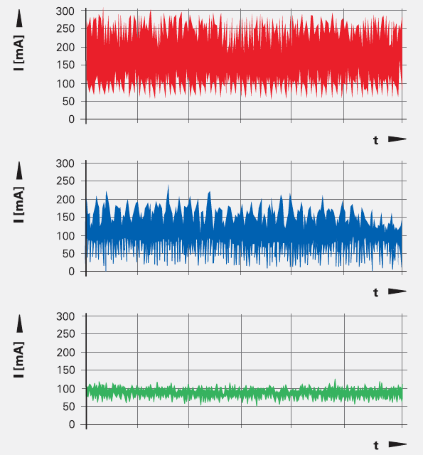
Current variations for different types of scanning systems in the encoders: resolver (top), inductive (middle), optical (bottom).
Bandwidth
Bandwidth (relative to command response and control reliability) can be limited by the rigidity of the coupling between the motor shaft and encoder shaft as well as by the natural frequency of the coupling. Encoders are qualified to operate within a specified acceleration range. Values typically range from 55 to 2,000 Hz. However, if the application or poor mounting cause long-lasting resonant vibration, it will limit performance and possibly damage the encoder.
Natural frequencies vary depending on the stator coupling design. This frequency needs to be as high as possible for optimal performance.
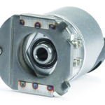
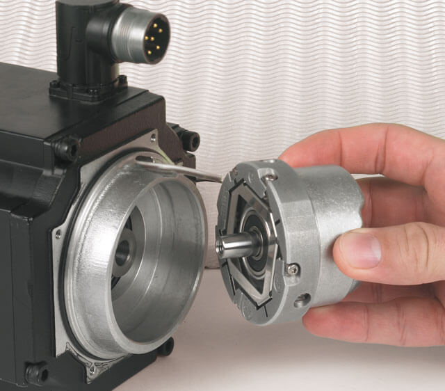
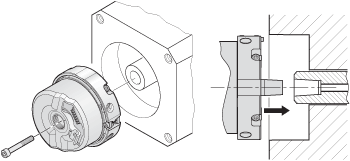
The key is to ensure that the bearing of the encoder and the bearing of the motor are as close to perfect alignment as possible. Figure 4 shows an example of how this is accomplished. The matching tapers of the motor shaft and encoder ensures near perfect alignment to the centerline.
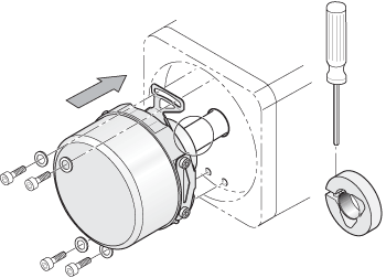
This mechanical configuration will result in a holding torque approximately four times greater than a standard hollow shaft encoder with a 2-mounting tab stator coupling, as shown in Figure 5. This will increase the bearing life of the encoder and provide exceptional natural frequency and acceleration properties. Additionally, this configuration will virtually eliminate any limits on the bandwidth of the drive!
In summary, many factors influence the selection of an appropriate rotary encoder for use in controlled servo drives. And while positioning accuracy requirements are paramount in the consideration process, it is important to know how other properties — such as speed stability, noise, possible power loss, and bandwidth — will influence the application. A good fit from the start will provide positive performance in the motor/drive system in the end.
Released date: October 11, 2021
Source: www.motioncontroltips.com