There are many motor types out there for engineers to choose from, and which is the best selection depends on each individual application. When deciding if a brushless servo could be the best solution for an application, asking a few basic questions can help.
For instance, does the application require:
• Small size and weight (torque density)?
• High efficiency?
• High reliability?
• Fast cycle time?
• Precise control of position, direction and/or speed?
• Predictable characteristics (torque constant (Kt), voltage constant (Ke), synchronous speed)?
If the requirements listed above are desirable — or essential -— for the particular application, then brushless servo motors could be the answer. The reason a brushless servo motor can achieve these characteristics is because of its design.
Small size and weight
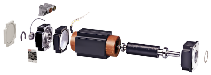
In most cases, brushless servo motors will be smaller in size and weigh less than similarly powered motors. This reduction in size is possible due to the design of the rotor and stator. A brushless servo motor uses permanent magnets (neodymium for the highest performance) attached to the rotor to create the rotor’s high-intensity magnetic field.
Motor manufacturers typically use one of two methods to insulate and protect the stator assembly windings; varnishing and encapsulating. Varnishing is the simplest of the two methods and uses an epoxy coating to protect the windings from contamination and electrical shorts.
While varnishing offers adequate protection for the stator windings, a better insulation method uses an insulating resin to fully encapsulate the windings. A motor that has its winding structure completely coated with an insulating resin can handle exposure to more severe atmospheric conditions than the normal varnished winding. This method not only protects the winding from contaminants, but also helps to conduct heat away from the windings better than air alone. Because of this, the motor can withstand more current without overheating — and more current translates to more torque. The ability of the stator windings to withstand more current without overheating, along with the strong magnetic field produced by the rotor magnets, allows the brushless design to provide small package sizes that can produce torque comparable to other motor types that are as much as twice the size.
High efficiency
The primary reason for the servo motor’s high efficiency can be attributed to the rotor design. As mentioned previously, the rotor’s magnetic field is generated by permanent magnets. The magnets can be part of an interior design (magnets are inserted into slots in the rotor lamination) or an exterior design (magnets are affixed to the outer surface of the rotor). Other technologies such as field assisted synchronous reluctance (FASR) which boast IE5 (greater than NEMA Super Premium) efficiency also benefit from permanent magnet style rotors.
From an efficiency standpoint, the magnetic rotor design is superior to a typical induction motor because the induction motor must induce the rotor’s magnetic field, and there are losses involved with that technique. Those losses are eliminated with the permanent magnet rotor design. Also, brushless servo motors use power only when needed. Unlike some other technologies that waste power, servo motors use just enough power to satisfy the load requirements, and when they are not doing work, they don’t consume energy. Because the brushless servo requires a servo drive to operate, it can vary the speed when necessary. This helps the overall system efficiency because it can slow down the motor.
For example, in a pumping application, the flow can be controlled by varying the speed of the motor and the pump as opposed to turning a valve to throttle the pump. In this type of application, the affinity laws can be used to realize the energy savings. Flow is proportional to speed and power is proportional to the cube of speed. In a typical example, a reduction of 20% in speed can result in an almost 50% reduction in energy consumed.
High reliability and fast cycle times
High reliability
Reliability is built into the design of the motor. As mentioned previously, the stator can be encapsulated in an epoxy resin, which protects the windings from contaminants and holds the winding firmly in place. It also eliminates the unwanted effects of corona (electrical discharge caused by the ionization of air in the winding gaps) by eliminating the air that the corona effect requires.
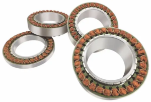
Bearings tend to be the weakest link when it comes to reliability, but in most cases, high-quality ball bearings that never require re-greasing (greased for life) are used. If a motor is properly sized for an application, it should provide many years of service with no required maintenance.
Fast cycle times
Although there are some instances where the application can’t withstand faster
cycles without effecting the quality of the product being produced, that’s certainly not always the case. The fact is, in most cases, if the task can be performed quicker, then throughput can be increased and the cost lowered to produce that item. Brushless servo motors are specifically designed with this kind of performance in mind.
Diameter
Brushless servo motors are intentionally designed with as small a diameter as possible and will typically offer several different lengths (stacks) in each frame size. When more power is required, a motor will be built longer rather than with an increased diameter. The reason for keeping the diameter as small as possible is to keep the inertia low. The lower the inertia, the faster the rotor can be accelerated and decelerated. Looking at the formula for acceleration torque below, it’s easy to see why. We’ll ignore the friction torque (Tf) for now.
Tacc = (Jt) (accel rate) + Tf
Because acceleration torque is limited to a given amount of torque dictated by the lesser of the drive or motor peak capability, if the inertia (Jt) goes up, then the acceleration rate goes down. Therefore, the inertia should be as low as possible.
J = 1⁄2 W/g(R2)
where:
J = inertia
W = weight
g = gravitational constant (386 in./sec2 or 9.81 m/sec2)
R = radius
Looking at the formula for inertia (J) the length affects the weight (W), but the diameter has a greater impact as the resulting radius value is squared (R2).

Precise control of position, direction or speed
Electronics have gotten better and faster, and servo motors and drives have benefited from this. Encoders can now provide millions of counts per revolution, and drives’ current, velocity and position loops have gotten fast enough to use all those counts. Because there is so much resolution, the motor can oscillate plus or minus 100 counts around the desired position; however, this deviation will result in almost no deflection from the desired position. For instance, an encoder with 23-bit resolution can provide more than eight million counts per revolution. If the motor oscillates +/- 100 counts, then what that means in mechanical deflection is +/- 0.004°. If the motor were connected to a belt and pulley, ball screw, or gearhead, there would be even less impact on the actual load. All this resolution results in tighter control of speed and position. Drive commissioning is easier, and inertia mismatches between the motor and load can be greater. All of these benefits are the result of improvements in the electronics used by the drive and encoder.

Predictable characteristics
Brushless servo motors have predict- able characteristics that can be useful to some applications. Servo drives can measure the amount of current being used by the motor. Application engineers can use this information to their advantage. For instance, if they wanted to know how much torque was being applied, they could look at the current being used by the motor. Since Kt is rated in Nm/A, if the amps are known then the torque can be calculated. For example, let’s assume a particular motor has a Kt = 1 Nm/A, and the current flowing through the windings of that motor measures 2 A.
Since 1 Nm of torque is generated for every amp of current, then 2 A would result in 2 Nm of torque. (2A x 1 Nm/A = 2 Nm).
Torque constants vary some with temperature, so as the current increases, the Kt value will change.
In many applications, this method of measuring torque provides adequate results. For critical applications, a torque transducer should be considered.
Another predictable characteristic is the voltage constant (Ke). Like a dc motor, if you back drive a brushless servo motor by using an external source to spin the motor shaft, a voltage will be generated (BEMF) across the motor windings. Typically, the Ke is rated in volts/1,000 rpm or (V/ krpm). If you were to back drive the motor shaft at 1,000 rpm and measure 100 Vac (BEMF) between the motor leads, then the Ke measured would be 100 Vac. With the Ke of the motor known, if you were to back drive this motor at 2,000 rpm, you would expect to measure 200 Vac.
The ac voltage can be measured across any two of the three motor leads with an ac voltmeter. For a Y-connected motor (three lead), this would be line-to- line voltage.
It’s much easier to back drive the motor and measure the Ke than it is to measure the Kt. For that reason, typically Ke is measured, and Kt is calculated
from Ke.
For example, if Ke = 100 Vac (rms), first convert Ke from V/krpm to volts/ radian/second (V/rad/sec).
Ke = 100 Vac (rms) = (100V / (1,000 / (60 / (2 * pi)))) = 0.9549 V/rad/sec
Then multiply V/rad/sec by 3, (0.9549 * 3) = 1.654 Nm/A = Kt
The last predictable characteristic to discuss is the synchronous speed. Unlike other technologies that can vary on speed (slip) as the load increases and decreases, a brushless servo motor runs at synchronous speed (no slip). Because the rotor’s magnetic field comes from magnets and is not induced from the stator, it will always rotate in sync with the stator’s magnetic field. For example, if you command 1,800 rpm the motor will rotate at 1,800 rpm, not 1,750 rpm, etc.
Although not all applications require brushless servo technology, it’s easy to see why this technology is the clear choice of many demanding applications. With increased demand for things such as electric cars, AGVs, robotics, and drones, the future demand for brushless servo motors looks better than ever.
Released date: Jan 11, 2023
Source: www.abb.com